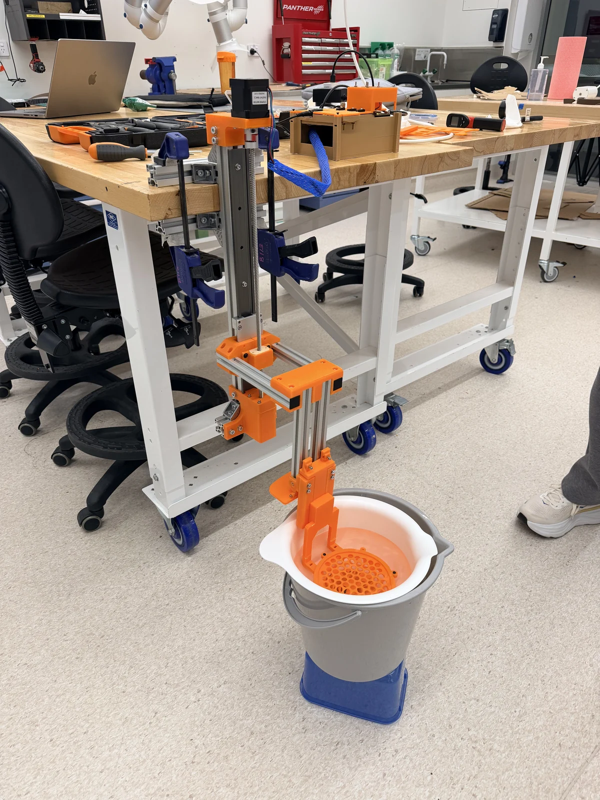
Explore how our assembled machine fits together, then check its configuration against dated photographs and test results. The interactive reconstruction shows the U02 controller and the curved 10 mm basket.
11 October 2026 · Curved-sieve water trial, without specimens. Later configuration confirmations are listed below.
Interactive review model · v0.7
Explore the latest modelled configuration.
Rotate, zoom, separate parts and toggle 42 model objects. U02 and the fan are visible with the frame and the curved 10 mm sieve assembly. Both 3 mm and 10 mm sieves have physical test records; one size is shown at a time.
The full model is loaded only when requested. Its compressed transfer is approximately 3.6 MB and may take a moment on mobile connections.
Physical installation, clearance and water-loaded operation have been checked at the scopes below. This reconstruction preserves source geometry and handedness, but it is not a complete as-built model. The controller is separate from the frame on the physical machine; its displayed location here is illustrative. Motion illustrates a 30 mm stroke at an uncalibrated speed. See component-by-component differences.
01 · CURRENT CONFIGURATION
Match the model to the machine.
Physical configuration follows the dated team records; button labels were confirmed on 17 October. Differences in the reconstruction are stated alongside each assembly.
Machine height
600 mm
Base width
235 mm
Maximum side width
300 mm
Measured on 12 October. These are separate named measurements, not a verified length × width × height envelope. Model geometry has not been rescaled.
Frame and moving assembly
Actual machine
Latest v3 carrier pair, standard and mirrored. Two 608-2RS bearings: one in the bearing holder and one in the motor bracket. Frame stability and connections checked.
The viewer represents the mechanism, but its carrier mesh has not been independently matched to v3. Only one of the two bearings is shown.
Interchangeable sieves and support
Actual machine
Both 3 mm and 10 mm curved sieves have completed water-only runs. The strengthened BR02 v0.3 support was confirmed on 12 October. One sieve is installed at a time.
The 10 mm curved basket, matching B05 lid and B02 six-screw ring are shown. The 3 mm alternative is not a second installed layer. The 11 October trials do not establish use of the later-confirmed BR02 revision.
Collection bowl and outlet
Actual machine
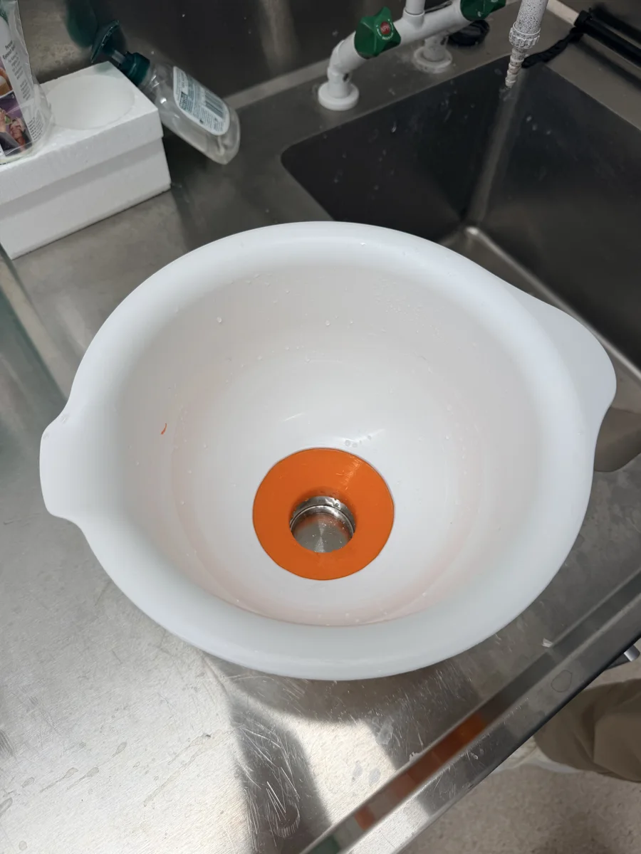
The IKEA collection bowl uses the modified Q01 outlet. Its continuous sloping interior replaces the earlier internal ledge. Leakage and residual-water checks are recorded.
The basin is representative. The Q01 outlet and detailed collection path are not modelled; use the dated photograph below.
U02 enclosure and fan
Actual machine
The 60 mm B01 body, U02 lid and fan are assembled as a separate controller, placed away from the wet area. The old frame spacer is unused. Fan airflow and cable clearance were checked.
The controller is displayed beside the frame for inspection. Its displayed position is illustrative; the physical unit is separate from the frame. Electronics are reference shapes and wires are omitted. CAD clearances are design references.
Controls and motion
Actual machine
Three active buttons: A (D2) up/faster, B (D3) down/slower, C (D4) start/stop. When stopped, hold A or B to position at 15 mm/s. During reciprocation, each A click increases the setting by 5 mm/s; each B click decreases it. Holding counts once; release and click for another change. Stroke is 30 mm. Settings span 10–75 mm/s, defaulting to 50 mm/s after reset. These are commanded settings. Fitted knobs remain inactive in the firmware.
Motion illustrates 30 mm travel; animation speed is not calibrated. The viewer does not simulate the firmware, switches or electrical protection.
Electrical configuration
Actual machine
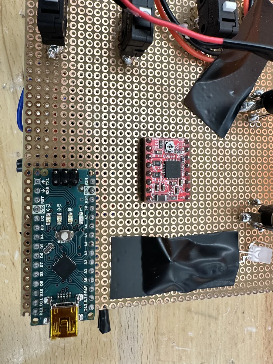
A 12 V, 3 A adapter supplies A4988 VMOT and the fan in parallel. Nano uses USB power and supplies 5 V to A4988 VDD, with common ground. Half-step mode is selected; ENABLE is grounded.
The diagrammatic electronics do not verify wiring. Measured VREF is 1.28 V with R100: a nominal calculated 1.60 A limit, not measured coil current. The adapter’s 3 A rating is supply capacity.
02 · PHYSICAL EVIDENCE
Look at the installed parts.
Dated photographs show the hardware behind the model. Open each image for a closer view.
Installed electronics
12 October 2026 · Physical board arrangement. Individual connections are documented in the controlled electrical record.
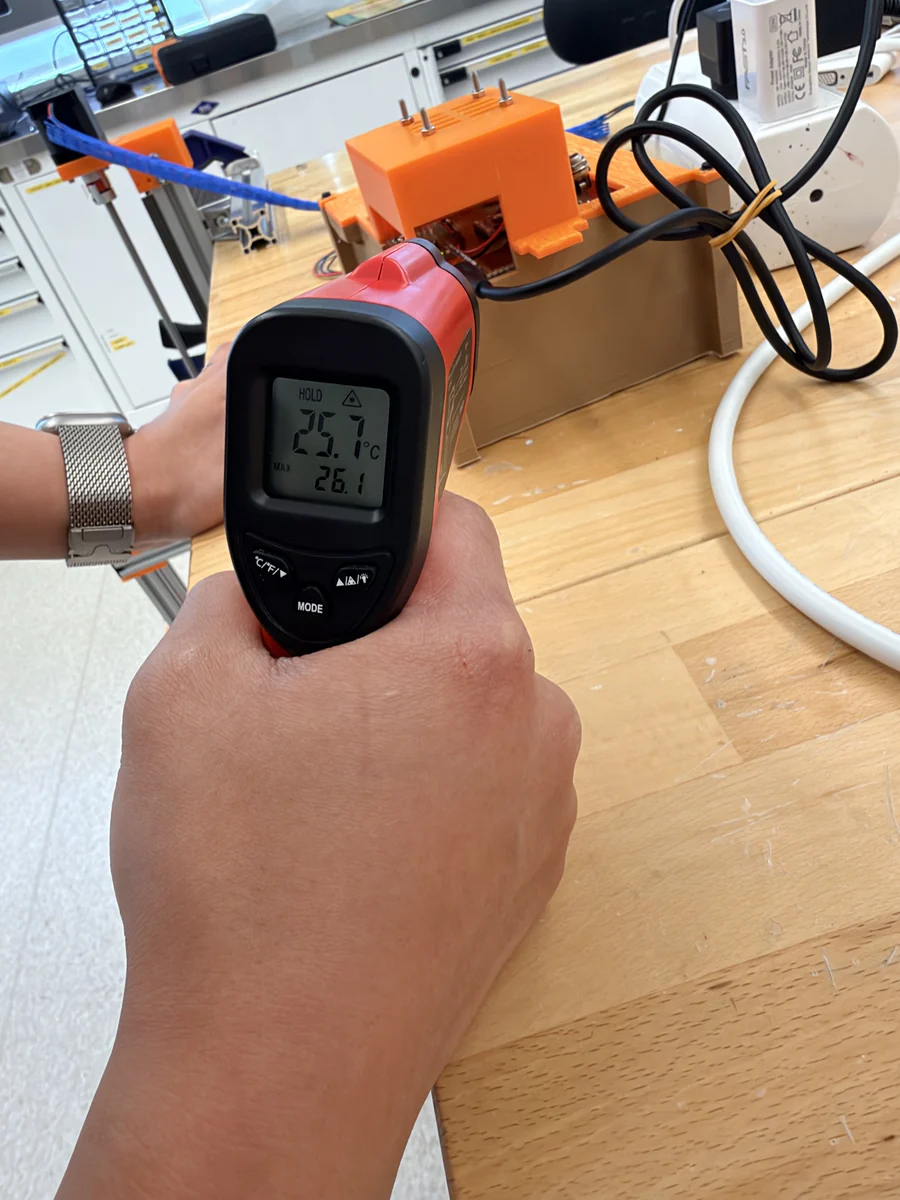
Measured after operation
12 October 2026 · A4988 post-run reading, 25.7°C. Linked to the 10-minute, 500-cycle water-loaded test.
Bowl and modified outlet
12 October 2026 · Residual-water observation. This collection detail is absent from the interactive model.
U02 controller close-up
The installed upper replaced U01 after support-removal damage. Inspect its shape and component reference positions separately.
The development sequence was the original glued bucket, a newly printed screw-fixed bucket with flat sieves, and then the curved sieves. Earlier results retain their original configurations and dates.
U01 is a superseded controller upper. Its reports describe design calculations and manufacturing estimates, not the current installed upper. U02 digital checks also remain separate from the later physical tests above.
The viewer retains geometry reconstruction v0.7. Content was updated on 21 October without representing the meshes as a complete as-built model.
CREDITS & PROVENANCE
Original work first. Team changes clearly separated.
This student reconstruction builds on EntoSieve, introduced by Ascenzi et al. (2025). Attribution does not imply that the original authors endorse this reconstruction or the team's modifications.
Original EntoSieve design and research
EntoSieve: Automated Size-Sorting of Insect Bulk Samples to Aid Accurate Megabarcoding and Metabarcoding
Aleida Ascenzi · Lorenz Wührl · Vivian Feng · Nathalie Klug · Christian Pylatiuk · Pierfilippo Cerretti · Rudolf Meier
The paper's contribution statement credits early and latest machine conception to Aleida Ascenzi and Lorenz Wührl; machine and component implementation to Lorenz Wührl and Nathalie Klug; and overall conceptualisation to Christian Pylatiuk, Pierfilippo Cerretti and Rudolf Meier.
The student team's review work includes the Stage 3 curved-basket assembly, the historical U01 candidate, the installed U02 controller upper, photo-informed lower-connection corrections and the evidence-linked visual reconstruction.
These project-specific changes are distinct from the original EntoSieve design. Case-specific physical results are retained separately; final project approval and acceptance remain outside the viewer.
Licence boundary · checked 1 Oct 2026
The journal article is published under CC BY 4.0. At the time checked, the public OSF node did not declare a licence for its separately hosted STL and 3MF files. This page therefore describes the displayed composite as a team working reconstruction, retains full attribution and does not claim that the paper's licence extends to those separately hosted model files.